


How to Specify a Titanium Orifice Flange
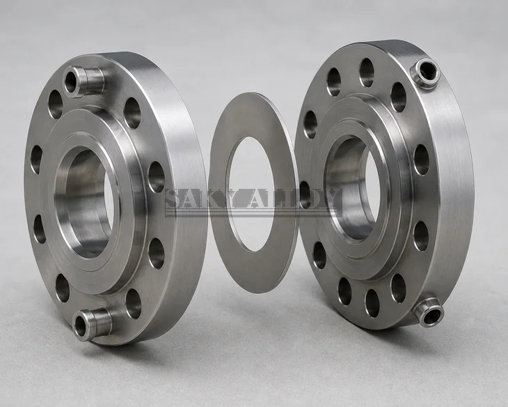
An orifice flange is one part of a differential-pressure measurement assembly. The flange pair, pressure taps, orifice plate, bore, gasket, bolting, piping geometry and instrument design must be specified as a system.
Assembly Definition Matrix
| Element | Required data |
|---|---|
| Flange pair | Standard/drawing, type, NPS, class, facing, bore and schedule |
| Pressure taps | Orientation, size, thread, plugs and access |
| Orifice plate | Material, thickness, bore, edge, tag and direction |
| Accessories | Jack screws, gaskets, studs, nuts and handles |
Confirm Standard Coverage
State ASME B16.36 or the approved project drawing and revision. Do not assume every flange type, class, size or custom tapping arrangement is covered. Out-of-scope configurations require an approved design basis.
Measurement-System Responsibility
Beta ratio, flow calculation, straight-run length, tap location, plate orientation and instrument selection belong to the measurement-system design. Material supply alone does not validate measurement accuracy.
Material and Quality Requirements
Define titanium grade, material standard, service medium, temperature, corrosion review, dimensions, NDE, MTC and traceability. Confirm mating pipe, gasket compatibility, bolting and installation orientation.
Review the Product
See Titanium Orifice Flange and the Titanium Flange category.
RFQ Checklist
- Standard/drawing, type, size, class and facing
- Bore, schedule, taps and orientation
- Plate and all required accessories
- Grade, service and corrosion review
- Inspection, NDE, certificates and traceability
FAQ
Is the orifice plate automatically included?
Do not assume; list the plate and every accessory in the RFQ.
Can flange supply validate the flow calculation?
No. Measurement-system engineering must approve the calculation and installation.
Related Reading
Special Flange Selection · Long vs Standard Weld Neck · Reducing Flange RFQ