

How to Order a Titanium Reducing Flange
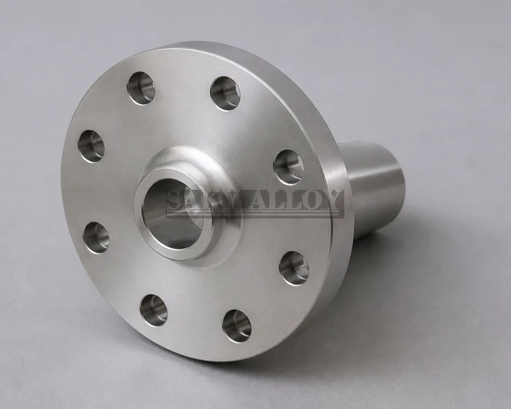
A reducing flange combines a flange connection with a smaller line-side bore or hub. Both nominal sizes and the complete transition geometry must be identified.
Required Data
- Flange nominal size and reduced pipe size
- Pressure class or PN and dimensional standard
- Facing and finish
- Large and small bore, transition length and profile
- Hub, pipe schedule and weld-end bevel when applicable
- Flow direction and installation envelope
- Titanium grade, material standard, quantity and NDE
Check Hydraulic and Mechanical Design
The reducer geometry can affect pressure drop, erosion, turbulence and drainage. The piping designer must approve transition direction, length and service suitability.
Alternative Arrangement
A standard flange plus separate reducer may sometimes simplify replacement or standardization. Compare space, welds, pressure design, maintenance and total cost.
View Titanium Reducing Flange or the Titanium Flange category.
Related Reading
Special Flange Selection · Orifice Flange RFQ Guide · Long vs Standard Weld Neck
Direct Answer: How to Order a Titanium Reducing Flange
Specify both the flange size and the reduced bore or mating-pipe size. A complete order includes titanium grade and forging specification, flange NPS, reduced NPS or bore, pressure class, flange type, facing and finish, dimensional standard or controlled drawing, hub/socket/thread geometry, bolt drilling, transition profile, quantity, NDE and documentation.
Required Reducing-Flange Data
| Item | Required definition |
|---|---|
| Material | ASTM B381/ASME SB381 grade or approved source specification |
| Connection | Weld neck, slip-on, socket, threaded or drawing-specific arrangement |
| Sizes | Flange NPS/class and reduced bore or mating-pipe OD/NPS and wall |
| Facing | RF, FF, RTJ or drawing-specific face and surface finish |
| Transition | Bore alignment, taper, hub or socket, wall and weld preparation |
| Inspection | Dimensions, facing, bore, bolt pattern, MTC, traceability and required PT/UT |
Selection and Design Boundaries
A reducing flange is not merely a standard flange with an undersized drilled hole. The transition must coordinate with the mating pipe, weld end or socket, pressure design, flow path and code requirements. Review pressure drop, erosion, dead-leg potential, bore alignment and the remaining ligament around the reduced opening.
For a weld-neck design, provide the small-pipe wall and weld preparation so the hub transition can be reviewed. For a socket-weld or threaded configuration, state the exact socket or thread standard, engagement and sealing arrangement. A separate reducer plus standard flange may be preferable where a gradual transition, maintenance access or standard replacement strategy is required.
FAQ
Which size is listed first?
State the flange nominal size and pressure class, then the reduced bore or mating-pipe size. A drawing is recommended because naming conventions can be ambiguous.
Can a plate flange be used?
Only when the governing design, material specification and engineering approval permit it. Do not substitute plate-cut material for a forged pressure-rated flange automatically.
What should be included with an RFQ?
Send grade, forging and dimensional standards, class, flange and reduced sizes, type, facing, transition drawing, quantity, service, NDE and certificates.
Titanium Reducing Flange | Titanium Weld Neck Flange | Request a quote